10 Ampere D.C analog Panel Instrument Repair !!!
This panel instrument below belongs to my good friend George. He removed it from a salvaged power supply along with a volt meter of the same manufacturer. Having myself seen at its back side an HC marking, I guess that it is a Hung Chang product (of Korean origin) but I am not quite sure about it.

I have in my mind cases having burned coil or bent/broken indicator needle pointer or non linear behavior of the instrument rendering it useless, but it’s first time I heard about such a case. So I took the instrument with me in order to investigate what was wrong with it.
When I ran the first test on it, I had a flowing current of 5A and indeed its indication was approximately 2,7A. Unfortunately, I was so much absorbed from its symptom trying to understand why this was happening, that I forgot to take a comparative photo of this first test (with another measuring instrument connected in series with it).
I started then to dismantle it. I removed the indication panel and its mechanism block. All I saw therein was what I expected to see.
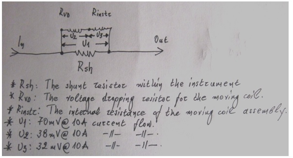
There were: the internally installed shunt resistor made of approximately 2,5 cm long wire which was also about 2mm thick. (I didn’t take any exact measurements on mechanical dimensions as there was no reason for this). It had a Z shape, with its ends connected to the external terminals of the instrument. A short piece of very thin diameter cable in black color was connecting one terminal of the shunt directly to the instrument’s mechanism. Finally at the other end of the shunt there was a voltage dropping resistor made out of special thin wire, wound like a coil, connected there with its one end. Its appearance was very similar to an R.F. air cored coil. The other end of this wire was connected to the other terminal of the instrument’s coil mechanism.
So the instrument’s coil was connected in series with the voltage dropping resistor and then this set was in parallel connected to the shunt resistor.
Their connection is shown below:
The index containing relevant additional info refers to the analysis I did during its repair process. You will understand it by further reading…
As I could not understand what was going on, I started to analyze the circuit.
First of all I wanted to test the instrument itself as a stand alone mA meter and check first its behavior, especially if its indication was linear throughout its entire dynamic range, because it would be irreparable in case it revealed non linear behavior.
In order to do this, I removed the voltage dropping resistor from the circuit by desoldering its one end from the instrument’s coil mechanism. Then I used my Mastech 7020 analog multimeter as a current source for the test. I selected its Rx10Ω range, in which it gives a full scale output of 15mA.
You can see below the Ω ranges of this multimeter along with the full scale current (: namely when its output terminals are short circuited) provided to its test terminals per each selected range.

By the way, it is worth saying here that there is a good reason for avoiding to test any small signal diodes or transistors or even LEDs using the Rx1Ω range of an analog multimeter, as this can very likely destroy their silicon crystal.
My instrument gives an output current of 150mA in this range (as you can see in the photo above) and in general all analog instruments of the market give similar output currents in this range.
Another important fact as regards these instruments is that when measuring Ω, the negative terminal of the instrument is the positive pole of its internal test current source, whereas its positive terminal is the negative pole of the source. In other words we have polarity reversal at its test terminals.
This usually confuses beginners when testing semiconductor components as they (logically) think that they apply the test signal with its correct polarity and weirdly the P and N junctions, which practically are respectively the anode and cathode ends of the diode under test, are found to be in reverse arrangement within the component than the expected one and therefore this effect is causing them a lot of confusion. For this reason this effect should always be taken into account during relevant tests. Similarly, of course, P-N-P transistors look like being N-P-N and so on…
To avoid this confusion when testing semiconductors (instead of normal resistors where polarity of course doesn’t matter) you can simply reverse the connection of your probes to the multimeter terminals (that is, the red probe to be put to the black receptacle and the black probe to the red receptacle).
And finally here is a practical tip in order for you to protect the needle pointer of your precious analog multimeter when carrying it with you for the various testing tasks in the field.
During carrying it, you should always have preselected beforehand its lowest volts range (in other words its microampere range as shown in the above photo) having also its COM and V/Ω /A inputs short circuited together. In this way, the needle pointer will not move freely here and there any longer by the usual vibrations developed on the body of the instrument due to your walking or to the transportation means moving and the instrument will remain absolutely safe and immune to vibrations.
This trick is based on the fact that after doing all above the short circuit is applied directly to the terminals of the microampere meter of your multimeter and therefore it acts as an electrical brake. The effect is similar to your try to revolve the rotor of a short circuited permanent magnet D.C motor. You will realize that you cannot revolve it and you will feel the strong “braking” effect in your hand when you try it.
Back to our topic now. Having myself selected the 15 mA current source I connected on the negative terminal of the multimeter and in series with it the positive terminal of the D.U.T (= device under test). Its free negative terminal was then connected to one end of a 5KΩ linear trimmer potentiometer. The wiper of the potentiometer was preset to its maximum resistance and then connected to the plus terminal of a digital multimeter set to measure mA D.C (:20mA range). The free negative terminal of the digital multimeter was going directly to the free end (positive) of the analog mutlimeter and the circuit was already closed, ready for the test to start.
The connection is shown in the schematic below:
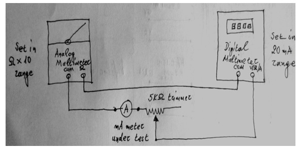
I started testing by gradually reducing the potentiometer’s resistance in order to see the current changes in the indicator panel of the D.U.T and compare them to the current flow indication of the digital instrument.
To make things easy for the linearity test, I chose to add before each next step of the procedure an amount of 0,65A to the value of the previous step, which represented 1A indication on its display.
Performing the test I created a table as shown below:

Now dividing each digitally indicated current by its respective analog indicated one, as shown below, the resulting values were found equal to each other:
0,65/1=1,3/2=1,95/3=2,6/4=3,25/5=3,99/6=4,55/7=5,2/8=5,85/9=6,5/10=0,65
This means that the above table is an absolutely convincing proof that the mA meter as a stand alone instrument was in perfect operating condition.
Right afterwards I measured the voltage drop on the D.U.T terminals, when its indication was in full scale. It was 32mV referenced to 6,5mA flowing through the D.U.T, when it was indicating 10A.
At this point I was “stuck” indeed! The rest of the circuit was only wire resistances that never change in value. In case of excessive current flow through them they simply get burned. But this is practically impossible for an amps meter to happen.
A shunt resistor can withstand an enormous amount of current before being destroyed in this way and the thin-wire voltage dropping resistor would need that enormous current flow through the shunt to get destroyed along with the moving coil of the instrument as well.
The information I had available so far from the above “road map”, was that I had a 6,5mA D.C meter, with its moving coil having a resistance of:
Rinstr= U/I → R= 32mV/6,5mA=4,92mΩ → 5mΩ (rounded up)
Then I connected a 5W car-lamp in series with the shunt and (being to approximately near to 12V output from my PSU) I measured 2,5mV for 0,36A current flow. This means again that the value of the shunt resistor was:
Rsh= U/I → R= 2,5mV/360mA=6,94mΩ → 7mΩ (rounded up)
This in turn means that with a current flow of 10A through the shunt resistor there will be a voltage development at its ends of the order of:
U=R*I=7mΩ * 10A=70mV
Therefore for a full scale display of the analog instrument needing 32mV, there are in excess:
70mV-32mV= 38mV to be dropped
For this drop a dropping resistor is needed, having a value of:
Rvd= U/I → R= 38mV/6,5mA=5,84Ω
I verified that this value was correct with that coiled resistor therein, after an additional Ω measurement on it.
So everything was perfect but the instrument was faulty…Very weird indeed…
I began thinking about it all over again. Then I remembered that when I desoldered the coiled resistor from the instrument’s terminal and trying to pull it in order to see its connection of the other end, this left me with the feeling that on its way from the shunt’s terminal up to the instrument’s coil assembly it was somewhere stuck.
Seeking a logical explanation for all of this weird effect, I removed again completely the coil assembly of the instrument and put it under a magnifying lens, supplying also plenty of light to it. Then I noticed that at approximately the middle of the shunt resistor’s body there was a stain…
It was now clear to me what happened with this instrument.
The hand- made voltage dropping resistor was put inside there in a wrong way, right from the manufacturing date of this instrument. Some turns of it were touching the shunt resistor’s body. When the shunt was repeatedly heated enough over time because of the flowing current through it, little by little this heat destroyed the insulation of the voltage dropping resistor at their touching point and the electrical effect of this short circuit was the equivalent of having a shunt installed therein having almost the half value than the needed one for these 10A of full scale display. This short circuited condition would need almost double current flow in order to drive the moving coil to its full scale…
That’s why the original indication I had in my first test, before doing anything else with it, was approximately 2,7A for an actual current flow of 5A exactly.
Note as well that this instrument, when working at 10A current flow, develops a power drop on it of the order of:
P = I2 * R = 102A * 7mΩ = 0,7W
And this loss manifests itself always as heat on the shunt’s body. Over time, even being of such a small magnitude, this thermal loss is nevertheless capable of causing such a weird failure… The case I had in front of my eyes was simply a proof of this argument to be actually true.
You can see the comparative measurements, after the repair, in the pictures below:

Of course many of the readers may say that such an effort for a cheap analog panel instrument was not worth repairing it, but I am already very well aware of this fact.
The point is that on one hand I just love these instruments because I was grown up using them and I feel very sad realizing that in our days they tend to disappear rapidly. George on the other hand had done so much of hand-work for its mounting in the front panel of his power supply while he could not find the same instrument all over Athens and he was desperate about it.
And this was the right time for a good friend to get involved and give a helpful hand! Despite the time I spent with it, this was a good refreshing exercise for me and hopefully a good tutorial for many of you the readers of this article.


Tidak ada komentar: